Automatic Identification of Ships (AIS)
AIS was introduced to assist the crew of a vessel in the identification of other vessels. In situations where it was necessary to call a nearby ship to avoid a collision, knowing the name of the nearby ship clearly helped to ensure that the correct vessel responded to the call. Previously, when just using an on board ARPA radar, calling a vessel using a phrase such as “vessel off my starboard bow” was not a guaranteed way of ensuring that the right message was received by the right vessel. The mandatory fitting of an AIS transponder to each SOLAS vessel means that every vessel transmits its ID and position at regular intervals. When integrated into the Bridge system of many ships, this provides an ID alongside the radar targets on the main ARPA and ECDIS displays and therefore enables the Officer on Watch to call a vessel by name.
For VTS and Coastal Surveillance, AIS enables all vessels within the Surveillance Area to be automatically identified. The AIS ID is displayed alongside the radar plot data and correlated with the extracted radar target data. AIS can provide much more information about the vessel, including its type, size, cargo and destination etc.. This information can be extremely useful in understanding the purpose of the voyage and more detailed information about the vessel itself to help ensure safe navigation. However, the additional information is all entered manually and therefore there are no guarantees that it has been entered correctly. Even the ships name is entered manually and there is no standard convention as to how it should be entered, or when. So if a ships name is changed, there is no guarantee that the AIS ships name will be updated on its AIS transponder.
Basestation or Transponder
For VTS systems (located onshore), the use of a mobile transponder (Class A or Class B) is not permitted. Mobile transponders are for use by ships. AIS Basestations or AIS Receivers can be used onshore. Most VTS Installations select an AIS Basestation as it has the ability to transmit its own position on every net cycle and will thereby appear on the ECDIS display of an approaching vessel. In addition, where a VTS system comprises a number of remote radar sites and therefore multiple AIS Basestations, all basestations can be set up with the same virtual MMSI so that the port only appears on the Ships ECDIS display in one location instead of identifying all of the sensor sites. AIS Basestations also provide additional functionality that could benefit VTS Operations, but is rarely set up and used. This includes being able to transmit text messages to ships and Aid to Navigation information to mark existing objects (using synthetic or virtual AtoNs) and the facilities to use binary messages for other value added functionality. An AIS Receiver may also be used onshore but only receives AIS information transmitted by ships.
Radar Sensors
The radar has always been known as the primary sensor of a VTS or Coastal Surveillance System. It detects all targets that are within line of sight of the antenna and have a radar cross section that enables enough of the transmitted power to be reflected and detected by its receiver. There are many types of radar sensor available and the VTS Manual provides guidance on key parameters that are relevant for VTS systems. However the selection of a radar sensor for a VTS, Coastal or Offshore application should be determined by an assessment of the type of targets that need to be detected and the resolution required to resolve each individual target when two or more targets are in close proximity to each other.
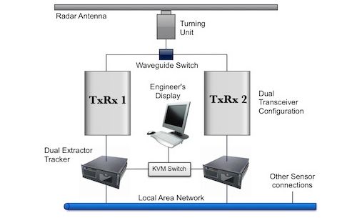
The siting of the radar will have an impact on the equipment configuration that should be deployed. If the site is remote and would take many hours to visit for maintenance purposes then duplicated equipment configurations should be considered.
Solid State Radar
“Solid State” is the term that has been applied to modern Pulse Compression Radars. Such radars achieve improved range resolution and signal to noise ratio. This means that the radar can provide the range resolution benefit of short pulse transmission at greater ranges. In a traditional Magnetron based radar, short pulse transmission would normally result in insufficient power being returned to the receiver for the target to be detectable at long range. To detect targets at long range, the radar would normally be set to medium or long pulse but this would have the effect of reducing range resolution. Pulse Compression (Solid State) radars will therefore help users to resolve two targets in close range proximity at longer range. Azimuth (Bearing) resolution is unchanged as this is a function of the antenna.
Pulse Compression radars use a longer pulse length with frequency modulation or phase coding to resolve targets with overlapping returns. Using a longer pulse width also enables the radar to be of lower output power and this removes the need for the traditional, magnetron based, high power transmitter. In many traditional radars, particularly those based at remote sites, the reliability of the magnetron was a major reliability issue for users and therefore dual transceiver radar configurations are very common, particularly for remote radar sites (see radar sensors). Pulse Compression (Solid State) radars should therefore require less maintenance and may only need single transceiver configuration but site visits will still be necessary for most remote unmanned sites as other factors such as the antenna turning unit maintenance will still require regular preventative maintenance.
CCTV & Electro Optics
CCTV is often wildly misunderstood for VTS and Coastal Surveillance applications. Whereas, for radar, there have been definitions established about the key radar parameters for specific targets, the same has not been defined regarding the use of CCTV / Electro Optics. CCTV requirements can often be specified without any reference to the size and type of target that the camera is expected to detect and therefore many VTS Centres under or over specify the technical requirements of the camera.
For radar it is common to specify the minimum size of target that should be detected and the range at which it should be detected. The same approach could be applied to CCTV / Electro Optic surveillance. In fact, other fields of surveillance typically specify optical sensors based upon ranges for Detection, Recognition and Identification (Johnson Criteria).
- Detection is normally defined as being able to determine that an object is present.
- Recognition means that you can determine the type of object
- Identification means that the specific object can be discerned.
VHF Direction Finding (VHF DF)
VHF Direction Finding was originally used by VTS Operators to assist in identifying which vessel was calling the VTS Centre. However, since the deployment of AIS, all AIS equipped Ships have been broadcasting their identity at regular intervals and VTS Centres have been reading this identity to assist the VTS Operator in identifying all vessels. Therefore, the uses for VHF Direction Finding within a VTS system has now changed as it is only those vessels that do not have an AIS transponder that this sensor can now help to identify.
But identification of unknown vessels is not the only role of VHF DF. In a complex VTS area where there are many AIS equipped vessels on the VTS Operators’ screen, it can still take some time for the Operator to find the relevant Vessel ID on his Traffic Display screen. VHF Direction Finding provides an on screen bearing line to indicate the direction of the source of a VHF transmission. This quickly directs the VTS Operator to the location of the vessel with whom he is communicating. It can therefore provide value as an aid to the VTS Operator in complex vessel traffic situations.
In the Coastal Surveillance domain, Communications Direction Finding still has a role as it can be used to detect voice communication which could assist law enforcement activities. VHF and / or UHF Direction Finding could help to identify the participants involved in illegal / smuggling activities and through the use of multiple DF sites, could enable triangulation on the source of a suspicious transmission. As such targets are likely to be small, fast moving craft that may be designed to avoid radar detection, the Direction Finding equipment could help guide Interdiction forces to their target.
Pros & Cons for VTS
All sensor systems selected for VTS and Coastal Surveillance applications should be subject to a Cost Benefit Analysis and pulse compression radars clearly provide improved performance but also at a higher price. Therefore, it should be considered whether the improved performance will also improve the operational performance of the final system. The key question is whether the improved range resolution and small target detection capability at long range is required for the specific application. Is it important that small targets can be detected at greater range? and is it important to resolve two targets in close proximity to each other on the same bearing to the radar at longer range. Clearly there are applications where this capability is of benefit, such as applications where small vessels are used for illegal activities. If such vessels are fast moving, then earlier detection at greater range provides earlier warning and can increase to available interdiction response time. However, for other applications, potential users should assess whether the additional cost will deliver equivalent benefits.